


 +86 13777722188


01
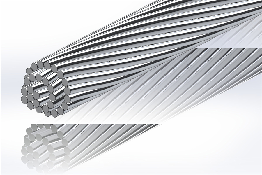


AAAC EN 50182 DIN 48201 All Aluminum Alloy Conductor
Product application
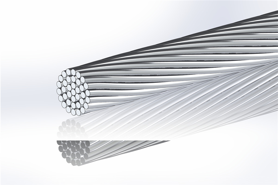
AAAC (All-Aluminum Alloy Conductor) is a high-performance alternative for power transmission, constructed from premium aluminum alloy to withstand mechanical stress. It outperforms pure aluminum in durability, thriving in coastal or industrial settings where corrosion is a concern, while ensuring consistent power delivery over extended spans.
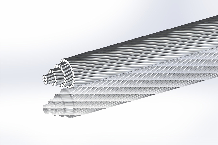
These conductors excel in mountainous or valley-crossing transmission projects, where their high tensile strength allows for longer spans between supports, reducing the need for excessive infrastructure.
AAAC Standard: EN 50182 (Old Standard: DIN 48201)
| Aluminum Alloy Conductor(AAAC) | |||||||||||
| Code Name | Old Code Name | Sectional Area | Wire Diameter&Stranding | Overall Diameter | Nominal Breaking Load | Linear Mass | Maximum Resistance at 20℃ | Modulus of elasticity | Coefficient of linear expansion | Current-carrying capacity | |
| mm2 | mm | No. | mm | kN | kg/km | Ω/km | N/MM2 | 1/K | A | ||
| 16-AL3 | 16 | 15.9 | 1.7 | 7 | 5.1 | 4.69 | 43.5 | 2.0701 | 60000 | 2.3x10⁻⁵ | 105 |
| 24-AL3 | 25 | 24.2 | 2.1 | 7 | 6.3 | 7.15 | 66.4 | 1.3566 | 60000 | 2.3x10⁻⁵ | 135 |
| 34-AL3 | 35 | 34.4 | 2.5 | 7 | 7.5 | 10.14 | 94.1 | 0.9572 | 60000 | 2.3x10⁻⁵ | 170 |
| 49-AL3 | 50 | 49.5 | 3 | 7 | 9 | 14.6 | 135.5 | 0.6647 | 60000 | 2.3x10⁻⁵ | 210 |
| 48-AL3 | 50 | 48.3 | 1.8 | 19 | 9 | 14.26 | 133.0 | 0.6841 | 57000 | 2.3x10⁻⁵ | 210 |
| 66-AL3 | 70 | 65.8 | 2.1 | 19 | 10.5 | 19.41 | 181.1 | 0.5026 | 57000 | 2.3x10⁻⁵ | 255 |
| 93-AL3 | 95 | 93.3 | 2.5 | 19 | 12.5 | 27.51 | 256.6 | 0.3546 | 57000 | 2.3x10⁻⁵ | 320 |
| 117-AL3 | 120 | 117.0 | 2.8 | 19 | 14 | 34.51 | 321.9 | 0.2827 | 57000 | 2.3x10⁻⁵ | 365 |
| 147-AL3 | 150 | 147.1 | 2.25 | 37 | 15.75 | 43.4 | 405.8 | 0.2256 | 57000 | 2.3x10⁻⁵ | 425 |
| 182-AL3 | 185 | 181.6 | 2.5 | 37 | 17.5 | 53.58 | 500.9 | 0.1827 | 57000 | 2.3x10⁻⁵ | 490 |
| 243-AL3 | 240 | 242.5 | 2.25 | 61 | 20.25 | 71.55 | 669.9 | 0.1373 | 55000 | 2.3x10⁻⁵ | 585 |
| 299-AL3 | 300 | 299.4 | 2.5 | 61 | 22.5 | 88.33 | 827.0 | 0.1112 | 55000 | 2.3x10⁻⁵ | 670 |
| 400-AL3 | 400 | 400.1 | 2.89 | 61 | 26.01 | 118.04 | 1105.2 | 0.0832 | 55000 | 2.3x10⁻⁵ | 810 |
| 500-AL3 | 500 | 499.8 | 3.23 | 61 | 29.07 | 147.45 | 1380.5 | 0.0666 | 55000 | 2.3x10⁻⁵ | 930 |
| 626-AL3 | 625 | 626.2 | 2.96 | 91 | 32.56 | 184.73 | 1730.5 | 0.0534 | 55000 | 2.3x10⁻⁵ | 1075 |
| 802-AL3 | 800 | 802.1 | 3.35 | 91 | 36.85 | 236.62 | 2216.6 | 0.0417 | 55000 | 2.3x10⁻⁵ | 1255 |
| 1000-AL3 | 1000 | 999.7 | 3.74 | 91 | 41.14 | 294.91 | 2762.8 | 0.0334 | 55000 | 2.3x10⁻⁵ | 1450 |
Note:
1.The outermost layer is twisted to the right (Z).
2. The elastic coefficients and expansion coefficients listed in this table are applicable to Germany. The calculation of other conductor structure parameters shall refer to IEC61597.
3. The flow rate values listed in this table are applicable under the conditions of a frequency of 60HZ, a wind speed of 0.6m/S, sunlight exposure in Germany, an ambient temperature of 35℃, and a conductor temperature of 80℃. In case of special laying conditions, the flow rate values should be reduced if there is no convection Less than 30%.